
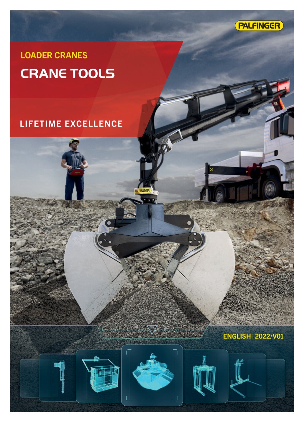
Palfinger Loader Cranes
Notice: Undefined variable: out in /mnt/wordpress_data/fo.kj/wp-content/themes/twentyseventeen-child/template_palfinger.php on line 281
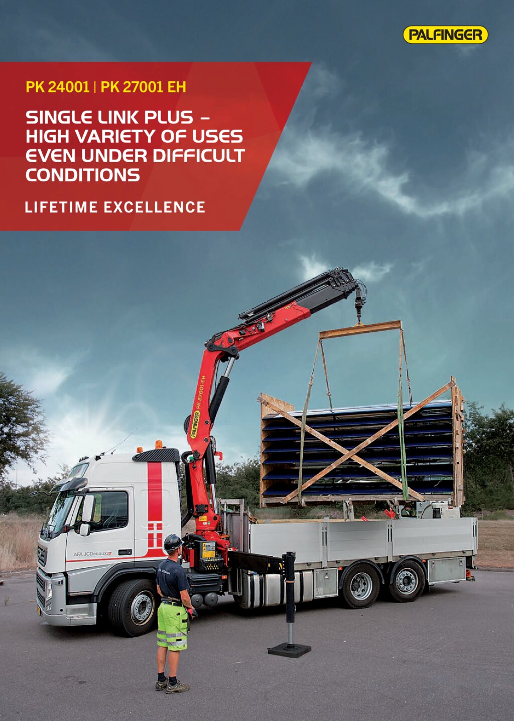
PK 24001 High Performance
Single Link Plus - High variety of uses even under difficult conditions
- High value retention thanks to coating technology
- High value retention due to coating technology
- Maximum utilisation of the working range due to HPSC
- Increased operating times due to low-maintenance extension system
- High degree of user-friendliness thanks to optional radio remote control
Brochures
PK 24001 / PK 27001 EH
| Max. lifting moment | 23.2 |
| Max. lifting capacity | 8500 |
| Max. hydraulic outreach | 21.3 |
| Slewing angle | 400° |
| Slewing torque | 2.8 |
| Stabilizer spread (std) | 5.0 m |
| Fitting space required (std) | 0.96 |
| Width folded | 2.55 |
| Max. operating pressure | 320 |
| Pump capacity | 50 - 75 l/min |
| Dead weight (std.) | 2538 |
Cranes shown in the leaflet are partially optional equipped and do not always correspond to the standard version.
Country-specific regulations must be observed. Dimensions may vary. Subject to technical changes, errors and translation mistakes.
Country-specific regulations must be observed. Dimensions may vary. Subject to technical changes, errors and translation mistakes.
Lifting moment | Outreach | Slewing angle | Slewing torque (mt) | Pressure | Pump capacity (l/min) | Crane Weight | Crane Height | Crane Width | Installation Width | Max stroke lenght | Max lifting capacity | Load vertical | |
|---|---|---|---|---|---|---|---|---|---|---|---|---|---|
| A | 23.2 mt | 8.1 m | 400 | 2.8 | 32.0 Mpa | 50-75 | 2578 kg | 2340 mm | 2550 mm | 955 mm | 7966.22 mm | 8500 kg | 2850 kg |
| B | 22.6 mt | 10.3 m | 400 | 2.8 | 32.0 Mpa | 50-75 | 2779 kg | 2340 mm | 2550 mm | 955 mm | 10146.22 mm | 8300 kg | 2050 kg |
| C | 22.1 mt | 12.5 m | 400 | 2.8 | 32.0 Mpa | 50-75 | 2959 kg | 2340 mm | 2550 mm | 1030 mm | 12326.22 mm | 8050 kg | 1560 kg |
| D | 21.5 mt | 14.6 m | 400 | 2.8 | 32.0 Mpa | 50-75 | 3136 kg | 2340 mm | 2550 mm | 1070 mm | 14506.22 mm | 7850 kg | 1160 kg |
| E | 21.0 mt | 16.9 m | 400 | 2.8 | 32.0 Mpa | 50-75 | 3282 kg | 2340 mm | 2550 mm | 1105 mm | 16736.22 mm | 6700 kg | 880 kg |
| F | 20.6 mt | 19.1 m | 400 | 2.8 | 32.0 Mpa | 50-75 | 3395 kg | 2340 mm | 2550 mm | 1105 mm | 18966.22 mm | 6600 kg | 670 kg |
| G | 20.3 mt | 21.3 m | 400 | 2.8 | 32.0 Mpa | 50-75 | 3504 kg | 2340 mm | 2550 mm | 1105 mm | 21196.22 mm | 6500 kg | 500 kg |
The outreaches stated are with a boom angle of 20° and are therefore not the maximum. When using mechanical boom extensions, the loads shown on the charts need to be reduced by the weight of these extensions.